At it’s most basic description, the Taranis transmitter and receiver work together to send a message to a servo to rotate either clockwise or counterclockwise from a center resting position. Our class focuses on configuring the Taranis so that the message correctly reflects your intentions. If we’re to understand how that happens, we need to understand at least a little about the language of that message. The concepts are important and are woven throughout OpenTX. We need to deal with this before going any further into Basic Airplane Set Up on Taranis.
The radio sends 50 messages a second over each active channel. Each message commands servo movement to a position either clockwise or counterclockwise from its centered resting position. The message takes the form of a voltage pulse with a longer lasting pulse calling for rotation in one direction and a shorter duration pulse for rotation in the opposite direction. A pulse lasting 1500uS (microseconds) corresponds to the centered position. A customary range of signals in RC radios is plus/minus 500uS on either side of the center position, so a typical operating range for servo signals could be 1000uS for full rotation on one side to 2000uS for full rotation on the other side. This form of messaging is called Pulse Width Modulation, or PWM for short. The “customary” part of that description is important to our Basic Airplane Set Up on Taranis class, so let’s consider industry standards and OpenTX defaults for a moment.
In PWM messages:
- A 1500uS center resting signal is common in radios but not consistently so. Some radio manufacturers use a slightly off-set center closer to 1515uS. The Taranis uses 1500uS as the default center signal.
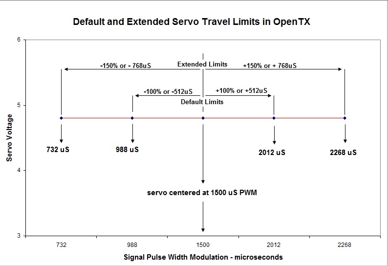
- Some radios use 1500 +/- 500 for full travel as described above. The default 100% travel on the Taranis is 1500 +/- 512uS, or 988uS to one side and 2012uS to the other side.
- Most computer-based radios allow travel to be extended beyond 100%, some to 120%, others to 140%. If the “extended limits” box is checked in “Model Set Up” on the Taranis (screen #2 in the Model Setting Menu), servo travel limits can be extended to 150% of the default, or +/- 768uS.
In servos:
- Full travel is plus/minus 45-degrees to either side in many servos but is only 40-degrees (or less) in some and a lot more in others. Some can even rotate a full 360 degrees.
- You would hope that an increasing PWM signal would at least produce a servo rotation in the same direction from servo to servo, but not so. Within a given brand, yes, but among different brands, there is no guarantee.
So… We have 50 messages per second in each channel and PWM coding as industry standards for radios and servos. Beyond that, there are no industry standards for direction of servo rotation, default amount of rotation, center position signal, or extended PWM signal limits. This makes it important that we understand the defaults and limits included in the Taranis.
A quick note about units of measure: If you checked the “ppmus” (pulse position modulation in microseconds) option in your build/download of OpenTX firmware, your Taranis will display PWM microseconds in the Servos screen and the channel monitor. Otherwise you will see “%” for servo travel in those screens, and the percent shown is the percent of the default 512uS deflection from center. The following graphic summarizes the Taranis defaults and limits.
If you’re questioning “Why is this important?”, please read on. A “weight” appears in three essential screens for our set up — Inputs, Mixer, and Servos. Each weight is expressed as a percent, and eventually all three weight percents are multiplied together to produce a combined weight that is the percent of the default servo travel limit of +/- 512uS to determine the signal to the servo:
net wt % in Inputs
(up to 100%) |
x | net wt % in Mixer
(up to 100%) |
x | % of Servo Travel Limit
(up to 100% or extended up to 150%) |
= | Percent of +/- 512uS travel signal to Servo |
This construction of the servo signal is the basis of the “command chain” logic that we use in this class. If it seems complicated, please don’t panic. We construct the logic step by step in the Basic Airplane Set Up with Taranis class. An example could use .75 as 75% weight in Inputs; 1.00 for 100% weight in Mixer; and 1.30 for 130% extended limit weight in Servos. If those were the three values in order above, 0.75 * 1.00 * 1.30 = 0.975 or 97.5% of the default 512uS for commanded travel to the servo. The resulting PWM signal would be 0.975* 512 = 499uS positive rotation from center or 1500+499uS = 1999uS. Although we didn’t exceed the 100% (or 512uS) final travel signal limit to the servo, we used 130% in the servo travel limit field, which would have required the Extended Limits box to have been checked.
It’s often said that there is no single “right” way to set up a model in OpenTX. That is especially true with advanced set ups that use the extraordinary flexibility of OpenTX to achieve a special goal. But in general there is a design to OpenTX that we can exploit to achieve predictable results and make troubleshooting easier. It’s that design that we will explore in Basic Airplane Set Up with Taranis.
A General Note of Caution: The Taranis with OpenTX generally offers more servo travel than other radios, and the settings on other radios are unlikely to be the settings you need on the Taranis. Please follow the instructions in this class carefully as though you were setting up a new model and do not try to simply transfer your existing settings to the Taranis.
Click to move on to Startup Warnings, Main Screens, and Model Selection (1/13)

